The membrane switch design for applications
The membrane switch is build with the membrane overlay and the membrane circuits which all with the silkscreen printing technology. The overlay layer printing the decorate/indication patterns or text on it's bottom, the silver conductive ink printing on the circuit layer. The two opposing layers are separated by a thin adhesive with a hole at the switch location. Finger pressure at the switch location deforms the overlays through the spacer hole and completes the bottom circuits. Tactile feel is provided by a embossed poly-dome or a snap metal domes.
The membrane switch is flexible and self-supporting but must be mounted to a rigid support. A common support can be a hard plastic enclosure, can be the metal plate or the aluminum plate. With our experience, the large dimension membrane switch suggest to mount to metal plate.
The membrane switch contain the below four components.
a. The membrane overlay.
The membrane overlay also call as the graphic overlay. It's a top layer of the membrane switch. Sometimes, the membrane overlay been used as a separate layer that without circuits. It's can be used as the labels, Or used as the Name-plate.
The membrane overlay design easy and cost effective. It can be design with the difference colors that you want to, it can be quickly design difference dimensions and shape. The membrane overlays have the rear adhesive on it's bottom and you can use them very easy.
b. The membrane circuit
The flexible circuit is used as the circuit of the membrane switch, the circuit can be build with the conductive silver that printing on the thinner flexible polyester sheets, the circuit can be build with the copper foils that use the Kapton as the basic, the circuit can be build with the hard PCB or the flexible PCB.
The conductive silver printed circuit is good for not a complex design, which the membrane switch don't need the very complex routing and no the many electric components solder, the such circuit can have the life-time more than five years. The PET circuit design pitch is better more than 1.0mm, and the routing lines suggest more than 0.4mm thickness, the more thickness routing circuits, the lower loop resistance. The process of the PET circuit also very environmental protection, and the cost is much more economy.
The copper flexible circuit also called the FPC, the FPC technology is more like the PCB, but the FPC circuit can't build with multilayer circuit routings. The FPC can be build with the thinner routing circuitry to be 0.1mm, and the pitch to be 0.3mm. The FPC use the copper as the conductive material, the loop resistance is very small, and the electric function is very stabilize. There can be very easy design and solder the electric components with the FPC circuits. The FPC circuit thickness is around 0.125mm, it's very flexible and the life-time is more than ten years.
The FPC have the advantage of the PET circuits and the PCB circuit, the cost of the FPC circuit also very high.
The PCB circuit is used very often in our life, the all electric products will need the PCBs design. Here the membrane switch also can design the PCB as the circuits. For the some design, there PCBs also can combine control and the electric function together, the PCBs bottom will solder the IC and the top side design the control keys. Normally, the PCBs circuit design will choose the solder connectors as the connection, and here we also can solder the FPC tails or the FFC wires that as the connection. Or use the hot-bar process that combine the PCBs and the flexible circuit together.
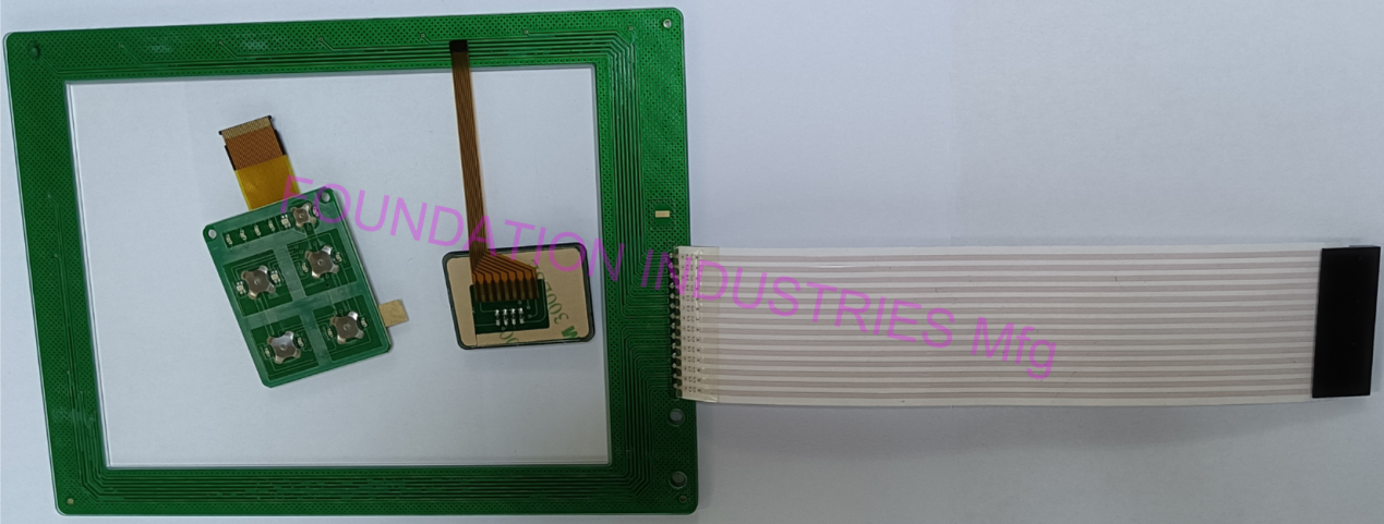
The membrane switch include a flex tail that is part of the same polyester sheet that contains the circuit conductors in the polyester&adhesvie keypad sandwich. Creasing, tearing, abrasion or vibration can easily damage the flex tail or the termination point at the end of the tail. The total length of the keypad flex tail plus the size of the keypad itself is constrained by the maximun size of the printed polyester sheet that can be printed.
Additional Benefits of using a rigid circuit bord
1. The additional electronic componets such as resistors, capacitors, diodes, and even integrated circuits can be incooporated into the membrane switch assembly.
2. The surface mounted LEDs can be directly soldered to the printed circuit bord, thereby eliminating potential intermittent or open LED circuits caused by stress.
3.The keypad interconnection to the application's electronics are greatly expanded as a wide variety of eonnectors can be solder on the rear side of the printed circuit board through cutouts in the meal or plastic support plate.
4.The connectors can be high density, throught-hole, surface-mounted, polarized, latching, or shielded.
5. The design is open and process blessed with experience.
Summary
The caused of poor reliability in conventional flexible siver printed membrane switch have been identified and a good solution has been advanced. It's more easy design than the traditional mechanical switch, it can express a beautiful appearance of decoration.
Along with solving the initial reliability problem of flexible printed membrane switch in mundane environments, using a thin printed circuit board in place of the layered printed polyester/adhesive provides vastly improved interconnection choices.
Incorporating other electronic components in the keypad is also comparable or lower total cost. The improved reliability using a thin printed circuit board in keypads allows the improved user interface keypad to be used in high reliability and harsh environments with improved overll system design, without increasing the cost.